
Load Flow Studies for Industrial Facilities: Why Nameplate kVA Isn't Demand
Nameplate kVA tells you almost nothing about actual demand. Here's why a load flow study built on real data changes the answer.
Pathworks Engineering Team

Sizing a distribution system off the simple sum of connected equipment nameplate ratings is one of the fastest ways to end up with an electrical system that is either badly oversized and needlessly expensive, or (more dangerously) a system that passes a superficial paper check and then trips, overheats, or experiences unacceptable voltage drop under genuine operating conditions. Nameplate kVA is a rating that describes equipment capability under specified conditions. It is not, by itself, a prediction of how a facility actually draws power over the course of a real operating day. A load flow study exists specifically to model the gap between the two, and skipping it in favor of a simple nameplate summation is a decision that tends to surface its cost only after equipment is already installed.
This article works through what a properly executed load flow study captures that a connected-load summation misses, the specific industrial load characteristics that most commonly get oversimplified, and what the actual deliverable of a competent study should look like.
What Connected Load Summation Leaves Out
Diversity and demand factor. Not every piece of connected equipment in a facility operates simultaneously at full nameplate load, and the National Electrical Code's Article 220 demand factor tables exist precisely because summing nameplate ratings across an entire facility systematically overstates actual coincident demand for most standard occupancy types. However, applying a blanket NEC demand factor to an industrial facility with a genuinely unusual load profile (batch process loads that cycle on and off in a defined sequence, large motor starting sequences that stagger equipment startup, or continuous-process loads that run at a stable percentage of rated capacity around the clock) can just as easily understate real demand if the facility's actual operating pattern isn't reflected honestly in the demand factor assumption being applied. Generic demand factors are a reasonable starting point for standard commercial occupancies; they are frequently the wrong tool for a facility whose load profile doesn't resemble the population of buildings those tables were originally derived from.
Power factor and reactive load. A facility with substantial induction motor load draws significant reactive power, measured in kVAR, in addition to real power measured in kW, and the resulting power factor affects both the apparent power (kVA) that the utility service entrance actually has to be sized to supply and, under many utility rate structures, the demand charge portion of the electric bill directly. A load study that reports only real power demand without separately characterizing power factor and the resulting reactive load is missing precisely the number that a utility interconnection agreement, and frequently a power factor correction capacitor sizing decision, will actually scrutinize closely.
Motor starting inrush current. A single large motor starting across-the-line can draw six to eight times its full-load running current for a period of several seconds during acceleration: a transient event that a steady-state demand calculation simply does not capture, because steady-state analysis by definition looks at the system after transients have decayed. This transient matters for two distinct reasons: it determines whether upstream voltage drop stays within acceptable limits at every other bus in the system during the starting event, since a large enough voltage sag can cause other running equipment to trip or malfunction, and it determines whether upstream protective devices are sized and set to ride through the inrush without nuisance tripping on what is a normal, expected operating event rather than an actual fault condition.
Harmonic-producing loads. Variable frequency drives, LED lighting drivers deployed at scale, and switch-mode power supplies used throughout modern industrial and commercial facilities all inject harmonic currents into the electrical system that increase effective RMS current beyond what a fundamental-frequency-only load flow calculation predicts. This harmonic content can require transformer derating, commonly expressed through a K-factor rating on dry-type transformers serving harmonic-rich loads, that a simplified demand study focused purely on fundamental frequency real power will not flag, and the omission can result in a transformer that is thermally overloaded despite appearing adequately sized based on a conventional kVA calculation.
What a Proper Load Flow Study Actually Models
A load flow, or power flow, study solves the underlying network equations for voltage magnitude and phase angle at every bus in the system under a specified set of operating conditions, typically using iterative numerical methods (most commonly Newton-Raphson or Gauss-Seidel) implemented in standard commercial power system analysis software. The output that actually matters to a real design decision is not a single system-wide summary number. It is bus-by-bus voltage, branch current, and system losses evaluated under multiple distinct operating scenarios: normal steady-state operating load, anticipated peak demand conditions, and the transient conditions present during motor starting sequences, particularly when the largest motor in the facility starts while the rest of the system is already operating near its typical peak.
This distinction is the difference between the claim "the transformer is rated for the sum of the connected load" and the claim "the system maintains acceptable voltage at the electrically farthest panel in the facility when the largest motor starts while the plant is already operating at eighty-five percent of its typical peak demand": and only the second, far more specific statement is something a genuine load flow study is actually equipped to answer with engineering confidence.
Modeling Multiple Operating Scenarios, Not Just One
A load flow study limited to a single "typical" operating condition provides an incomplete picture for any facility with meaningful load variability, which describes the majority of real industrial operations. A defensible study should, at minimum, model normal steady-state operation at anticipated average load, peak demand conditions reflecting the coincidence of the facility's largest simultaneous loads, and a motor-starting transient scenario for the largest motor or motor group in the facility, evaluated against the system already operating near peak. Facilities with significant seasonal load variation (heating and cooling loads that shift dramatically between summer and winter operation, for instance) often warrant separate seasonal scenarios as well, since a system validated only against a summer peak condition may behave quite differently under a winter peak driven by an entirely different set of loads.
Where a facility has redundant or backup power sources (an on-site generator intended to carry critical loads during a utility outage, for example) the load flow study should also validate that the generator's capacity, and the facility's transfer scheme, can actually support the intended critical load list under realistic conditions, including motor-starting transients on generator power, which behaves differently from starting the same motor on a stiffer utility source given the generator's typically higher source impedance.
Where This Connects to Drafting the Final Deliverable
A load flow study only delivers real value to a client once its outputs land in a genuinely usable form (panel schedules, one-line diagrams, and load summary tables that a permitting authority can review efficiently or that an EPC contractor's field team can act on directly without requesting clarification. We cover the specific drafting-quality bar required for that handoff in our companion piece on panel schedule drafting standards. A technically correct load flow study delivered only as a raw software export, without being drafted into the format the next party in the process actually needs to work from, creates precisely the kind of translation gap that Pathworks exists to close) the engineering can be flawless and still fail to deliver value if it never reaches the field in a usable form.
How We Approach This
Our electrical engineering team builds load flow models against multiple operating scenarios rather than a single steady-state snapshot, specifically because facilities with meaningful load variability (which is most real industrial and commercial facilities) are poorly served by a single-condition analysis. We size studies to reflect actual demand behavior, including motor starting transients and harmonic-producing loads, rather than defaulting to a generic demand factor pulled from a code table that may not reflect the facility's real operating pattern. See our Electrical Engineering Services page for more on how this work is scoped.
Conclusion
Nameplate kVA describes what equipment is capable of drawing under specified test conditions. It says almost nothing about what a facility actually draws under real, coincident operating conditions across a representative range of scenarios. A load flow study that models diversity, power factor, motor starting transients, and harmonic content honestly (rather than substituting a generic demand factor for genuine analysis) is what actually protects a facility from the voltage drop, nuisance tripping, and thermal overload issues that a connected-load summation cannot see coming.
References
- NFPA 70 (National Electrical Code), Article 220: Branch-Circuit, Feeder, and Service Load Calculations
- IEEE Std 399: Recommended Practice for Industrial and Commercial Power Systems Analysis (IEEE Brown Book)
- Related reading: Panel Schedule Drafting Standards: What Makes One "Build-Ready"
- Related reading: Selective Coordination: Why the Wrong Breaker Trips First
- Pathworks services: Electrical Engineering Services
Related articles
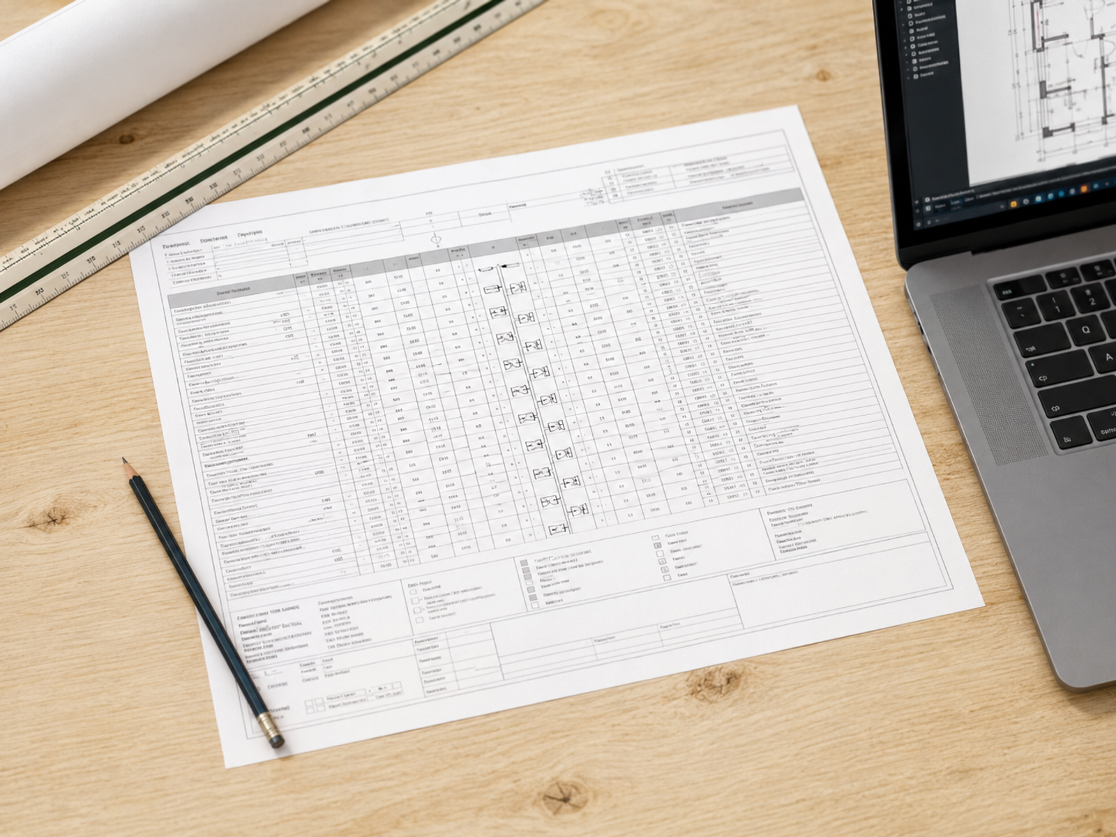

Panel Schedule Drafting Standards: What Actually Makes One Build-Ready
Most panel schedules pass a visual check and still fail in the field. Here's what actually makes one build-ready.

Short-Circuit Studies: What the Per-Unit Method Is Actually Calculating
The per-unit method isn't a shortcut, it's the actual math behind every short-circuit study. Understanding what it's calculating changes how you read the results.
Arc-Flash Studies Explained: What They Are and When You Need One
Arc-flash studies get requested reactively, usually after an incident or an audit finding. Here's what the study actually calculates and why waiting for a trigger event is the expensive way to find out you need one.